When getting started with model trains you typically start with an analog train. This means there is no communication with the train like setting the speed or changing direction via a digital interface. Instead, the locomotive has a motor that is connected to the track. Speed and direction are controlled via voltage that is applied to the track. To change the voltage, there is a switch you have to turn physically in order to move the train. Of course, you can purchase digital train systems to automate your layout, but these are more expensive and you might have an older train that you can’t upgrade easily. This blog post explains a way to automate an analog model train by adjusting the voltage automatically. There are some analog models which use AC motors but this blog post focuses on analog model trains with DC motors.
The blog post is divided into 3 topics
Electronic basics
Analog model trains run with a DC motor. A DC motor converts current into rotational energy to drive the train. Typically they rely on a flowing current that induces a magnetic field. If you want to learn more about these you can read the Wikipedia article which gives a good introduction to DC motors.
If you apply voltage, the motor runs. When the polarity is reversed the motor runs backward. So far so good, but no one wants a model train that always goes at full speed. So the physical switch of the model trains contains the electronics to adjust the voltage to achieve a smooth ride. There are two options to achieve different voltages.
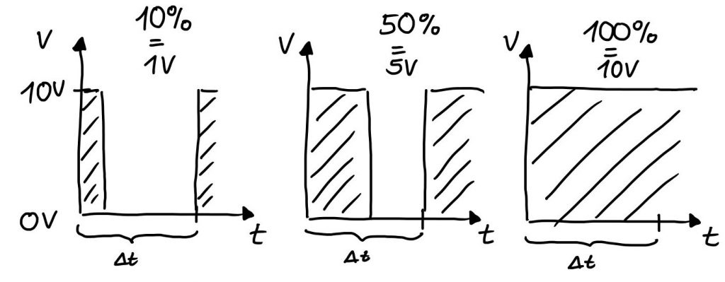
First, transform the incoming voltage to the target one. This requires different converters for different voltages or one with an adjustable output. These systems have a high power loss due to the conversion that dissipates energy as heat. Second, the more common option is to control the voltage with Pulse Width Modulation (PWM). This doesn’t require transforming the voltage. Instead, it periodically applies bursts of voltage for a certain amount of time. The PWM goes with a certain frequency and the time of voltage applied per period can be adjusted. This can range from 0% to 100% of the period of time and is called the Duty cycle. The output voltage equals the average voltage in one period. For example, the input voltage is 10V. The frequency is 100Hz (one hundred times per second). For each period the voltage is only applied 50% of the time. So every 100th of a second the 10V is applied for half the time of a period and turned off for the remaining time until the next period starts. The average output voltage is 5V and as a result, half the power is applied to the motor.
This works because the motor (and as a result the train) can’t react fast enough to the change in voltage due to the inertia of the moving mass. If the frequency is too low the motor will react to the slow change in voltage. Therefore, the frequency has to be high enough to avoid stuttering and vibration of the motor. If the frequency is high enough you won’t notice the switching of the voltage and the motor runs at a reduced speed. Using PWM has the advantage of having very little power loss because there is almost no voltage drop across the switch.
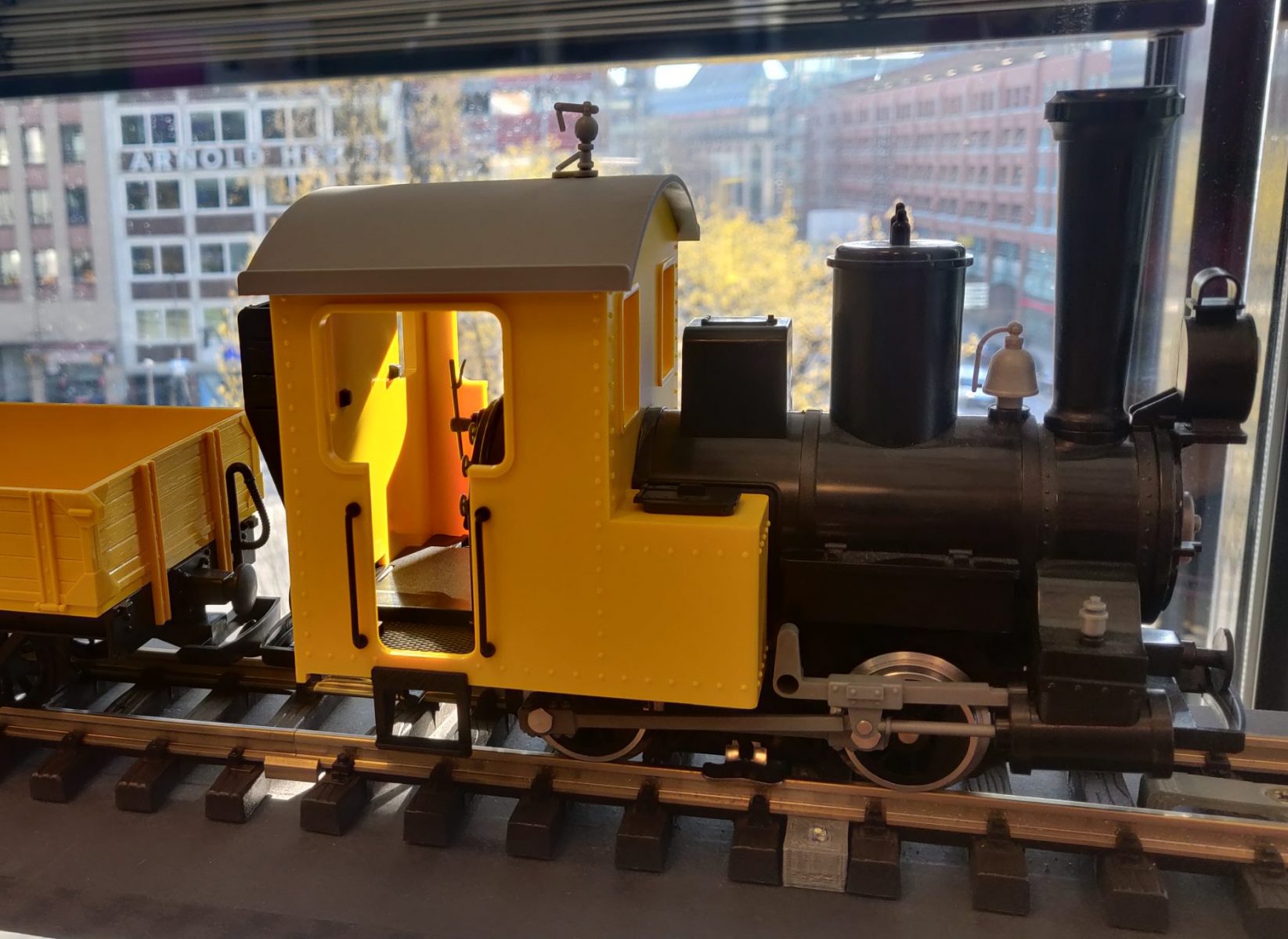
The analog switch I have for my model train also uses this method to control the speed of the train
H bridge
Now the speed of the analog can be controlled via PWM. Next is to enable the train to go back- and forward. Simple enough the DC motor turns the other way if the polarity is reversed. The physical switch for my analog model train uses a mechanical switch to change polarity. There are two possibilities to automate this behavior. First, attach some kind of motor to the mechanical switch which I determined to be unpractical. Second, use an electronic switch. So in order to automate an analog model train the electronics need to have two characteristics:
- allow for changes in speed with PWM
- control direction by changing polarity
The most common solution for this problem (which applies to almost all DC motors) is using an H bridge layout. It has four switches that can be configured. Depending on the configuration current flows in one or the other direction. So the motor can turn in both directions.
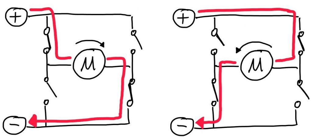
H bridge layouts typically allow PWM control. This makes it a great use case for using this kind of circuit.
Automation possibilities
There are different possibilities to drive the H bridge and set the PWM. You can use any device which has GPIO pins. GPIO pins (general purpose input output) are used to control any kind of device or read an input like a sensor. The H bridge is controlled via this kind of pins. Microcontrollers (e.g. an Arduino board) or a Raspberry Pi are commonly used. In the end, choose what you are most familiar with and/or based on your requirements. You can find code samples on how to set the GPIO pins for almost any platform/device online
Different ready-to-use boards with H bridge circuits are available. Before purchasing one for your project make sure that the board is suited for the voltage and rated power of your train.
In addition, you can set up sensors along the track to know when the train reached a certain position and possibly let it come to a stop. You can read the sensors from any free GPIO pin. Depending on your setup you can use a wide variety of sensors. For example, hall sensors or a light barriers, which might be easier to hide.